What are Electrical Symbols?
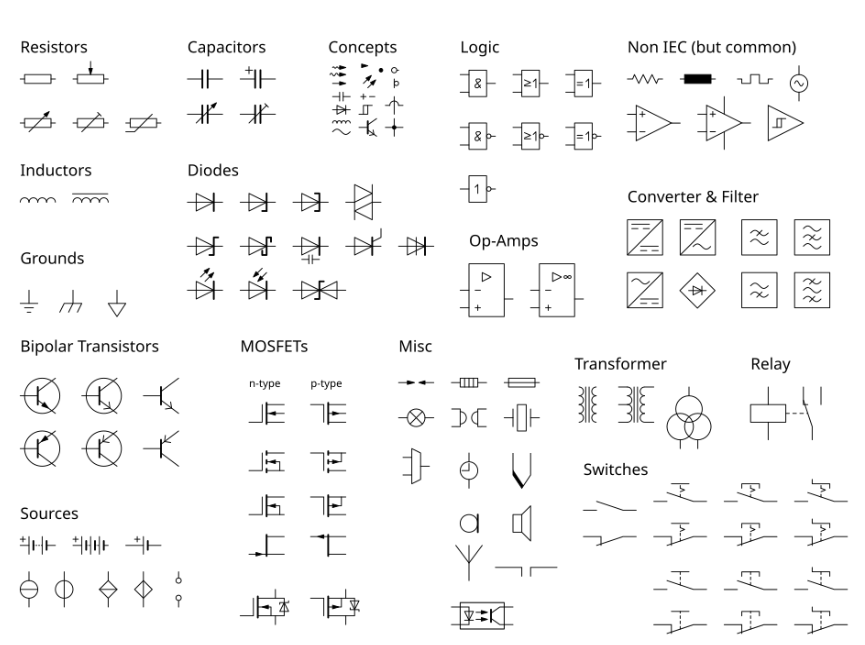
Think of a map. It uses symbols to show you where things are. A road, a river, a mountain. Electrical diagrams are just like that. They use a special set of pictures to show how a circuit works. These pictures are called electrical symbols. You need to know them if you want to understand how a device works. Learning these symbols is the first step to building or fixing anything electronic.
An electrical symbol is a simple picture. It stands for a real electronic part. A resistor, a battery, or a wire all have their own symbol. Using these symbols makes drawing a circuit easy. It saves a lot of time. And, everyone in the world who works with electronics uses the same symbols. It is like a universal language. This means a drawing made in one country can be read by a person in another country.
Basic Electrical Symbols Explained
Let's start with the most basic ones. These are the ones you will see most often.
First, there are power sources. A battery has a symbol that looks like a long line and a short line. The long line is the positive side. The short line is the negative side. An AC power source has a circle with a wavy line inside it. Ground is shown by a few lines that get smaller. You must know these symbols to know where the power comes from.
Then, there are the parts that use power. A resistor is a zigzag line. It slows down the flow of electricity. A capacitor looks like two short lines next to each other. It stores energy. An inductor is a coil or a loop of wire. It also stores energy. These are basic electrical symbols. They are in almost every circuit.
Then, you have switches. A switch is used to turn a circuit on or off. A simple switch is a line that can open or close a path. It looks like a lever. A switch can have more than one path. This lets the electricity go to different places.
You need to know wires. A wire is a straight line. It shows a path for electricity. If two wires cross and do not connect, they look like one line jumping over the other. If they do connect, they have a dot where they meet. Knowing these simple rules is key to reading a diagram.
Understanding More Complex Symbols
Some parts do more than just use power—they control it. One example is the diode, which looks like a triangle with a line at the end. It only lets electricity flow in one direction, acting like a one-way street. Another key part is the transistor. It is more complex, with three lines, and can work as a switch or an amplifier. There are several types of transistors, all with similar symbols. Learning these symbols makes it easier to see how a circuit makes decisions.
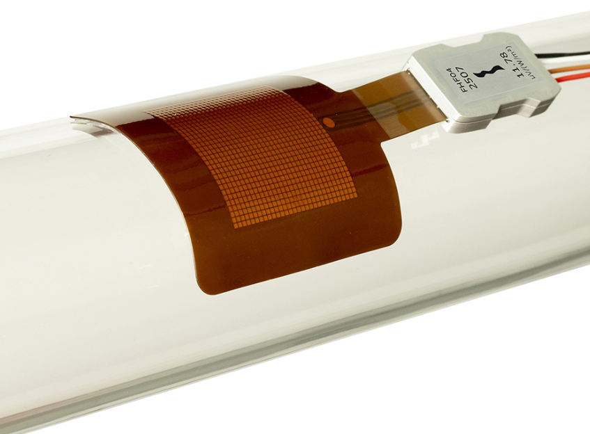
Symbols are also used for sensors. A sensor can detect heat, light, or pressure, and each type has its own symbol. Often the symbol is a circle with a few marks inside, showing that the part will change its signal based on what it senses. This is where sensor compliance becomes important. A sensor shown on a drawing must match a real part that follows set rules. Meeting these compliance standards is essential for the sensor to work correctly, and it is critical in many products.
For example, a heat sensor must work at the right temperature. A light sensor must work in the right light. Following sensor compliance rules makes sure that the real part and the symbol on the drawing match. It means the part will be reliable. Without good sensor compliance, a device could fail.
Reading a Full Circuit Diagram
Reading a full circuit diagram is easy if you know the parts. First, you find the power source. It is usually on the left or top of the drawing. Then, you follow the path of the wires. You see where the electricity goes. You find all the parts. You can see how they are all connected.
You should always start with power. Then, you follow the line. The line goes from one part to the next. You find the path of the electricity. This is the best way to understand a circuit. You can see how the parts work together. You can see how one part controls another. This process makes a complex drawing simple to read.
Why Standards Matter for Symbols
Electrical symbols we use follow simple rules. We call these rules standards. A few main standards are used around the world. IEC is used in Europe. ANSI is used in the United States. They make sure symbols match everywhere. This lets a person in Germany read a drawing from the USA.
Standards are important for many reasons. They make it easy to share ideas and to build products. Standards also help check if a product is made the right way. A person can see the drawing and then compare it with the real product to confirm it follows the correct rules. This is where sensor compliance becomes very important. A symbol on a drawing for a sensor must show that the real sensor meets the required rules and is reliable.
Tips to Learn Electrical Symbols
Practice is the best way to learn these symbols well. Find flashcards online to study. Look at simple circuit drawings to read. Try drawing your own basic circuits. This helps you learn and use the symbols. If a symbol is new, look it up right away. A good engineer never stops learning new skills ever.
You can start with simple circuits. A light with a battery and a switch is a good start. Draw it using the correct electrical symbols. Then, you can add more parts. You can add a resistor. You can add a diode. This helps you build your skills over time.
Conclusion
Understanding electrical symbols is like learning a new language. This skill is key for anyone who wants to work with electronics, since it makes it possible to read diagrams, build circuits, and fix problems. The symbols are simple pictures that follow clear rules, and knowing those rules shows how a circuit works. By turning complex ideas into simple images, symbols become an essential part of electronics.


