Trimmer Resistors: Precision Parts for Circuit Tuning
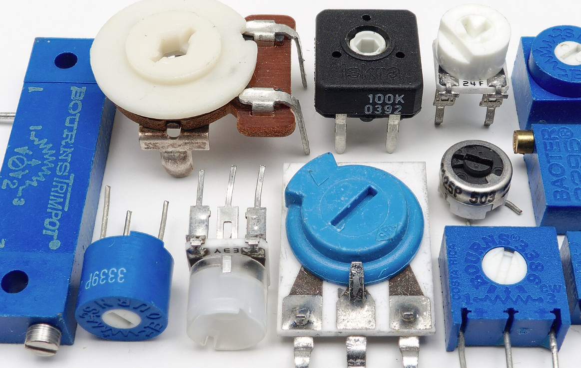
Trimmer resistors, also called trimmers or trimming potentiometers, are small adjustable resistors. Engineers use them to tune circuit values. Use them to set sensor zero, set amplifier gain, or tweak a reference voltage. They work in prototypes and in final products. They help meet tight specs without redesigning the PCB.
What does a trimmer consist of?
A trimmer resistor has three main parts: the resistive element, the wiper, and the terminals. Turn or slide the adjuster. The wiper moves on the resistive element. That change alters resistance between terminals. The amount of change depends on the resistive track and wiper position.
There are two broad kinds: mechanical and digital. Mechanical parts include single-turn and multi-turn types. Single-turn parts move fast but give low resolution. Multi-turn parts can take many revolutions. They give fine resolution and repeatable steps. Digital trimmers use I²C, SPI, or plain up/down lines. They let software change resistance. Fit remote and repeatable tuning tasks.

Key specs that shape your choice
Nominal resistance sets the tuning range. Power rating sets how much continuous power the part may dissipate. The temperature coefficient (TCR) shows how resistance changes with temperature. Linearity shows how close resistance moves to the ideal curve. Wiper contact resistance and noise affect low-level signals. Mechanical life tells how often you can adjust the part.
In short, a trimmer resistor is a simple tool. Use it smartly and it saves time and cost. Choose the right type and layout to avoid later problems.
Trimmer Resistor Basics
Basic operation and roles
A trimmer is a variable resistor. It can adjust the offset, trim gain, tune filters, or set thresholds. In power supplies, it can set the output voltage. In sensors, it will set zero and span. In amplifiers, it will match gains. The key value is a small, precise change, making circuit fine-tuning easy.
Single-turn trimmers move in one short sweep. They are good for coarse adjustments and for field use. Multi-turn trimmers use a screw drive or worm gear. They are slower but more precise. Top-adjust types let you tune from the top of the board. Side-adjust types let you tune from the edge. SMD multi-turn parts suit automated assembly and tight spaces.
Digital trimmers and programmable options
Digital trimmers use a resistor ladder and switches inside. A microcontroller can set the steps. They give repeatable, programmable control and remove mechanical wear and wiper noise. But they have limits — step size and often a limited resistance range. Use them when you need remote or frequent changes.
Key electrical specifications
Resistance : Sets the range. Common values: 100 Ω, 1 kΩ, 10 kΩ, 50 kΩ.
Power: The continuous dissipation rating. Overpower will damage the element.
TCR: Shown in ppm/°C. Low TCR means low drift with temperature.
Linearity and end-point error: Matter when setting gain or reference.
Wiper resistance and noise: Affect low-voltage readings and ADC inputs.
Mechanical life: Given in turns or cycles. Multi-turn parts may rate 200 to 2,000 turns.
Environmental and mechanical points
Humidity, salt spray, and vibration can harm the wiper contact. Dust and grit cause noise. For harsh environments, pick sealed parts or add conformal coating after calibration. Locking features or glue can stop unwanted movement in the field.
Selection, Design, and Production
First, state the function. Is the trimmer for a one-time factory trim or for user adjustment? Is it for coarse offset or fine calibration? Does it connect to ADC inputs, op amp nodes, or power feedback? These questions set the resistance range, precision, package, and power rating.
If you need remote control, consider digital trimmers or a DAC. If long-term stability is important, trim in production, then lock or replace the trimmer with a fixed resistor.
Resistance selection and noise tradeoffs
Resistance choice matters. High resistance lowers current and power use but raises thermal noise. Low resistance lowers noise but increases current and power loss.
Example: put 5 V across a 10 kΩ trimmer. Current I = 5 V / 10 kΩ = 0.5 mA. Power P = V × I = 2.5 mW. Choose a trimmer with a power rating 3× to 5× higher to be safe. For ADC references, keep source impedance low (often < 10 kΩ) so the ADC input sees a stable source. For battery or sensor nodes, high resistance saves power but increases noise.
Precision, linearity, and TCR needs
Precision work often needs 0.1% to 1% accuracy. Choose low TCR parts for thermal stability. If temperature swings exist, use low TCR fixed resistors plus a trimmer for final tweak. For very high accuracy, use trimmed fixed resistors or a calibration DAC.

Power handling and thermal layout
Do not place full current through a small trimmer if it must carry large power. Use a power resistor for the main dissipation and the trimmer for small adjustment. If the trimmer must see heat, place it away from hot components. Use thermal reliefs and copper pours to spread heat. Leave clearance for airflow if the board will get warm.
Orientation and assembly
For mass production, pick SMD multi-turn trimmers. For hand adjustment or field access, pick through-hole top or side-adjust parts. Plan orientation for easy tool access. If a trimmer must be adjusted after soldering, leave a tool access hole or slot in the enclosure.
For vibration-prone designs, pick lockable trimmers or those with mounting pins. After assembly, use glue or conformal coat to prevent movement.
Production trim flow and record keeping
Create a standard trim procedure: power up, warm-up, trim points in order, measure to target, log value, and re-check. Warm-up matters because references and parts drift during initial power-on. Log results to link to serial numbers and BOM.
Applications, PCB Layout, and Calibration
Common applications
ADC reference and input bias
Sensor zero and gain adjustment
Amplifier gain matching
Regulator output trim
Filter tuning and threshold setting
PCB layout best practices
Place the trimmer close to the node it adjusts. Keep traces short. Use wide traces for low-impedance paths. Keep sensitive analog traces away from high-current or noisy digital lines. Mark adjustments on the silkscreen.
Anti-vibration and environmental protection
Use trimmers with locking features or mounting tabs for vibration-prone designs. Seal with glue or conformal coating after calibration. For humidity and dust, use sealed trimmers.
Calibration and test steps
Power up the board and wait warm-up time
Measure the baseline at the target node
Adjust the trimmer to the target value
Let the measurement settle and confirm
Record the final value and any serial or lot data
Mark the part as calibrated or sealed
Summary
Trimmer resistors are a low-cost, effective way to fine-tune circuits. Choose parts by function, environment, and production needs. Balance resistance, power, precision, and TCR. Use multi-turn SMD parts for automated high-precision production. Use digital trimmers when you need remote or repeatable tuning. Good PCB layout and a clear production trim flow raise reliability and repeatability.
FAQ
Single-turn or multi-turn?
Use single-turn for quick, coarse trim; multi-turn for fine and repeatable trim.
Why does trim drift with temperature?
Common causes: high TCR, wiper contact change with heat, or proximity to heat sources.
Can a trimmer handle high power?
Usually not — use a power resistor for main dissipation.
Are SMD trimmers less reliable than through-hole?
SMD trimmers often give better assembly consistency; through-hole is easier for field adjustment.
How to keep production calibration consistent?
Use a standard flow: warm-up, trim order, instrument, and record. Automate when possible.


