What Is a Rheostat?
Sometimes we need to make a motor spin faster or slower. We achieve this control by changing the flow of electricity. One of the simplest and oldest parts used for this job is a rheostat. You can think of it as a special kind of gate or valve for electric current. Opening the gate allows more current to flow, and closing the gate a little bit reduces the flow.
This simple part is the foundation of many things we use every day. It is a fundamental building block in electronics that helps us manage power. Understanding how it works can open up a new level of appreciation for the technology around us. This guide will explain everything in very simple words. We will look at what this device is made of, how it does its job, and where you can find it.

How Does a Rheostat Work?
To understand how this device works, let's imagine a long road. If you want to drive from one end of the road to the other, it takes some amount of time and energy. Now, imagine you could change the length of that road. If you make the road much longer, it will take more energy to travel its full length. If you make the road very short, it will take much less energy. This is exactly the idea behind a variable resistor.
An electric current is like the car traveling down the road. The road itself is made of a special material that resists the flow of electricity. We call this the resistive element. A rheostat has three main parts that work together.
The Resistive Element: This is the "road" for the electricity. It is a track or a wire made of a material that does not let electricity pass through it easily. This material creates resistance. The longer the path the electricity has to travel along this material, the more resistance it will face.
The Wiper: This is the movable part. You can think of it as an exit ramp on our road. The wiper is a small contact that can slide or turn to touch the resistive element at any point along its length. By moving the wiper, you change the point where the electricity can get off the road.
The Terminals: These are the connection points. There are usually two connections used in a typical setup. One terminal is connected to the start of the resistive road. The second terminal is connected to the wiper.
Here is how it all comes together. The electric current enters the device through the first terminal at the start of the resistive road. Then, it travels along the resistive material. It keeps going until it reaches the spot where the wiper is touching the road. At that point, the current leaves the resistive road and flows out through the wiper’s terminal.
When you move the wiper, you change the length of the resistive road that the current must travel through. Moving the wiper to the far end makes the electric path very long, which means there is high resistance. A lot of resistance makes it hard for current to flow, so only a small amount gets through. Moving the wiper close to the beginning makes the path very short. This means there is low resistance, and it is easy for a lot of current to flow. So, by simply turning a knob or sliding a lever, you are directly controlling the amount of electric current in a circuit.
The Main Rheostat Applications
Because this device is so good at controlling current, it has been used in many different ways over the years. Its simplicity makes it a great choice for jobs where you need direct, hands-on control over power. Some of these uses are less common today with modern digital controls, but they are still important in many areas.
One of the most classic uses is in lighting control. Old dimmer switches for household lights were often large rheostats. To dim a light bulb, you need to reduce the amount of current flowing to it. A rheostat placed in the path of the current does this perfectly. Turning the dimmer knob moves the wiper. This increases the resistance in the circuit. More resistance means less current can get to the bulb, so the bulb shines less brightly. Turning the knob the other way decreases the resistance, which lets more current flow and makes the bulb brighter. This method works well, but it does create some waste heat, which is why newer digital dimmers are more common in homes now. However, for stage lighting in theaters or for special scientific lights, these powerful variable resistors are still used.
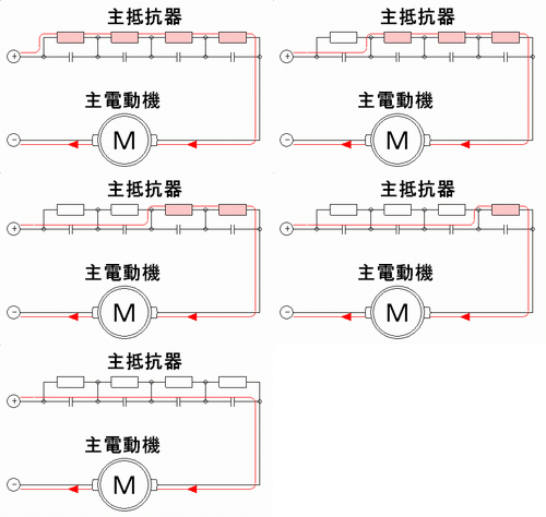
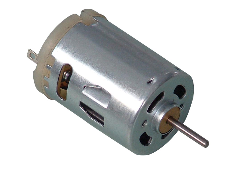
Another very common job is controlling motor speed. Simple electric motors, like the ones in fans, toys, or small tools, spin faster when they get more current. Their speed reduces when they get less current. You can put a rheostat in the circuit with the motor to act as a speed controller. When you want the fan to run at full speed, you set the device to its lowest resistance. This lets the most current flow to the motor. If you want the fan to slow down, you increase the resistance. The reduced current makes the motor spin more slowly. This is a very simple and effective way to get variable speed control without needing complex computer chips. Power tools, conveyor belts, and even some small electric vehicles have used this method.
Controlling heat is another area where these parts are useful. Electric heaters and simple ovens work by passing a large current through a special wire that gets very hot. To control the temperature, you need to control the amount of current going to that heating wire. A high-power rheostat can do this job. By adjusting its resistance, you can change the current and, therefore, change how hot the heating element gets. This can be found in laboratory hot plates, soldering irons with temperature control, and some industrial heating processes where precise and simple heat management is needed.
Even in sound equipment, these devices have played a role. Early amplifiers and radios sometimes used them to control volume. While this job is now almost always done by a similar part called a potentiometer, the basic idea was the same. By controlling the current to certain parts of the audio circuit, you could change the loudness of the sound. The feel of turning a smooth knob to adjust something is a direct result of these simple, effective components.
Understanding Different Types of Rheostats
Not all of these devices are the same. They come in different shapes and sizes, and they are made for different kinds of jobs. The main differences are in how they are built and how much power they can handle.
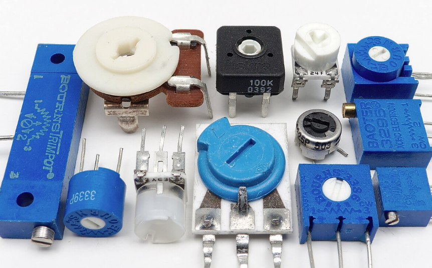
Perhaps the most common kind is the rotary rheostat. This is the type you probably picture in your mind, with a knob that you turn. Inside, the resistive element is formed into a circular or arc-shaped track. The wiper is attached to a shaft that the knob turns. As you turn the knob, the wiper sweeps across the circular track, changing the resistance. These are used in things like light dimmers and speed controls where a simple turning motion is easy for a person to use.
Another popular kind, especially in science labs and for testing, is the slide rheostat. Instead of a circular track, this type has a long, straight resistive element, often a wire wrapped around a ceramic tube. The wiper is a contact that slides along a rod mounted above the element. You move the slider back and forth with your hand to change the resistance. These are great for educational settings because you can clearly see all the parts and how the position of the slider affects the circuit.
There are also wire-wound rheostats. These are the heavy-duty workers. They are designed to handle a lot of power and heat. The resistive element is made from a special type of metal wire that is wrapped around a core, usually made of a ceramic material that can withstand high temperatures. Because they are built to be tough, wire-wound types are used for controlling motors and heaters that use a lot of current. Their construction makes them very durable.
For jobs that do not involve a lot of power, there are carbon composition rheostats. In these, the resistive track is made from a mixture of carbon powder and a binder, pressed into a solid shape. The wiper slides along this carbon track. These are cheaper to make than wire-wound types but cannot handle much current. You might find them in older electronic devices for small adjustments.
Potentiometer vs Rheostat: What is the Difference?
People often get confused between a rheostat and a very similar-looking part called a potentiometer. They can look almost identical on the outside, often with a knob and three connection points, or terminals. The biggest difference between them is their main job and how they are wired into a circuit.
A potentiometer is designed to be a voltage divider. Its main job is to control voltage. It uses all three of its terminals. One terminal is connected to a power source, another is connected to the ground, and the middle one (the wiper) gives an output voltage that changes as you turn the knob. Think of a volume control on a stereo. It sends a variable voltage signal to the amplifier, not a variable current.
A rheostat, on the other hand, is designed to control current. Its main job is to be a variable resistor. It only needs two connections to do this: one at the start of the resistive element and one at the wiper. Its purpose is to resist the flow of current directly.
Here is the interesting part: you can use a three-terminal potentiometer as a rheostat. This is done very often in electronics. To do it, you simply use two of the terminals. You connect your circuit to one of the end terminals and the middle wiper terminal. The third terminal is left unconnected or sometimes connected to the wiper. When wired this way, the potentiometer stops acting as a voltage divider and starts acting just like a two-terminal variable resistor. It directly controls current, which is the exact job of a rheostat. So, while they have different primary designs, a potentiometer can be made to do the work of its close cousin.
A Look at the Rheostat Symbol
In the language of electronics, we use symbols to draw maps of circuits. These maps are called circuit diagrams or schematics. Every part has its own unique symbol so that anyone can understand how the circuit is built.
The symbol for a rheostat is very simple and easy to recognize. It is based on the symbol for a regular resistor, which is a zigzag line. The rheostat symbol starts with this same zigzag line. Then, it adds an arrow that points to the middle of the zigzag line. The zigzag line represents the resistive element. The arrow represents the movable wiper.
This symbol perfectly shows what the device does. It tells you that it is a resistor, but the arrow shows that its value is not fixed. The arrow means you can adjust it. Seeing this symbol in a circuit diagram immediately tells an engineer or a hobbyist that at this point in the circuit, the current can be controlled by changing the resistance.
Simple Guide to Rheostat Wiring
Wiring one of these devices into a simple circuit is not very difficult, but it has to be done correctly for it to work. The most important thing to remember is that a rheostat is wired in series with the part you want to control. "In series" just means it is placed directly in the path of the electricity.
How to Choose the Right Rheostat for Your Project
If you are building something and need to control current, you need to pick the right part for the job. Choosing the wrong one can cause it to fail or even be dangerous. There are two very important numbers you need to look at.


