How to Convert 4-20 mA to 0-10 V Using Resistors
Resistor Voltage Drop
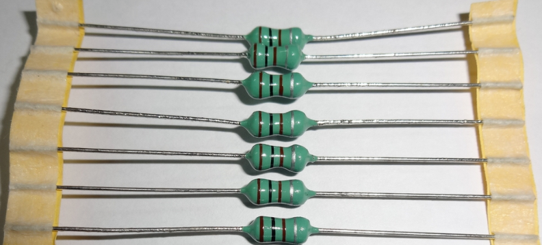
Understanding the concept of resistor voltage drop is fundamental when converting a 4-20 mA current signal into a 0-10 V voltage signal. In essence, when an electric current flows through a resistor, a voltage is developed across it according to Ohm’s Law, which states that V = I × R. This voltage drop is the key principle behind simple resistor-based conversion methods. For a 4-20 mA current loop, selecting the right resistor ensures that the voltage drop corresponds accurately to the current flowing through the loop, thus translating the current signal into a proportional voltage signal.
In practical terms, when a resistor is placed in series with the current loop, the current passing through it causes a voltage drop. At the lower end of the current range, 4 mA, the voltage drop will be minimal, while at 20 mA, the voltage will be at its maximum. This voltage range can then be scaled to fit within the 0-10 V output range, making it compatible with many data acquisition systems, PLCs, or other control devices. Understanding how the voltage drop varies with current is crucial for selecting the appropriate resistor value, ensuring linearity, and maintaining signal integrity.
This fundamental principle allows engineers and technicians to design simple and cost-effective interfaces between current-based sensors and voltage-based measurement systems. It also emphasizes the importance of precise resistor selection and wiring to achieve accurate and reliable signal conversion, especially in industrial control where signal fidelity is paramount.

Resistor Value Calculator
Calculating the correct resistor value is a vital step in converting 4-20 mA signals to 0-10 V. The goal is to choose a resistor that produces a voltage within the desired output range when subjected to the maximum current (20 mA). To determine this resistor, use Ohm’s Law: R = V / I. Since the maximum voltage you want is 10 V at 20 mA, the resistor value should be R = 10 V / 0.02 A, which equals 500 ohms.
For the lower end of the current range, 4 mA, the voltage drop across this resistor will be V = I × R = 0.004 A × 500 ohms = 2 V. This means the voltage will vary linearly from approximately 0.8 V at 4 mA to 10 V at 20 mA, assuming the resistor is precisely 500 ohms. If you want a different voltage span or a different output range, adjust the resistor value accordingly. For example, a smaller resistor will produce a smaller voltage change, which might be suitable for certain applications, while a larger resistor will increase the voltage span but may introduce issues like power dissipation and signal distortion.
To facilitate this process, many engineers use resistor value calculators available online or in engineering software. These tools allow for quick input of the desired voltage range and current range, providing the optimal resistor value. Proper calculation ensures that the voltage output remains within the specified limits, avoiding saturation or insufficient signal levels, which could compromise the accuracy of the measurement system.
How to Wire Resistor
Wiring the resistor correctly is straightforward but essential for accurate signal conversion. The resistor should be connected in series with the current loop transmitter, meaning it is placed in line with the current flow. Typically, the wiring involves connecting one terminal of the current source (the transmitter) to one end of the resistor, and then connecting the other end of the resistor to the input terminal of the measurement device or data acquisition system. The other terminal of the current source completes the circuit back to the transmitter, forming a closed loop.
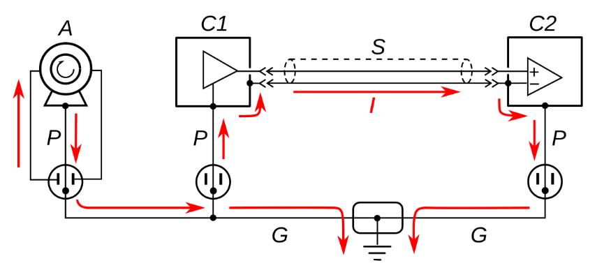
Ensure that the resistor is rated for the power dissipation expected in the circuit, which can be calculated as P = I² × R. For a 500-ohm resistor at 20 mA, the power dissipation is P = (0.02)² × 500 = 0.2 W. Using a resistor with at least a 0.5 W rating provides a safety margin. Proper wiring and secure connections are vital to prevent noise, signal loss, or potential damage. Using shielded cables or twisted pairs can help maintain signal integrity, especially in industrial environments where electromagnetic interference (EMI) can distort signals and lead to inaccurate readings.
Furthermore, it’s important to double-check the wiring diagram before powering the system, ensuring that the resistor is correctly placed and that all connections are insulated and secure. Proper grounding and shielding practices will help mitigate noise and ensure a stable, accurate measurement output.
Current Loop Transmitter
The current loop transmitter is a device that generates a 4-20 mA current signal proportional to a measured variable, such as temperature, pressure, or flow rate. These transmitters are designed to operate reliably over long distances, with the current signal remaining unaffected by voltage drops or electrical noise. They are commonly used in industrial automation and process control systems because of their robustness and simplicity.
When working with a current loop transmitter, understanding its output characteristics is crucial. The transmitter provides a stable current signal that can be easily converted into a voltage signal using a resistor, as discussed earlier. Properly powering and wiring the transmitter ensures accurate readings and consistent performance. Many transmitters include features such as calibration, filtering, and diagnostics, which can help maintain signal quality over time. These features are especially valuable in environments where electrical noise or temperature variations could affect signal integrity.
Choosing the right current loop transmitter depends on the specific application requirements, including measurement range, accuracy, and environmental conditions. Ensuring compatibility with the existing control system and proper installation techniques will maximize the benefits of using a current loop transmitter in your automation setup.
4-20mA to Voltage Conversion: Basic Principles
The conversion of a 4-20 mA current signal into a 0-10 V voltage signal relies on the linear relationship between current and voltage across a resistor. By selecting an appropriate resistor, the current range of 4-20 mA is mapped onto the voltage range of 0-10 V. This process involves understanding the proportional relationship and ensuring that the resistor value is such that the maximum current (20 mA) produces the maximum voltage (10 V).
This conversion method is favored for its simplicity, cost-effectiveness, and reliability. It allows standard voltage measurement equipment to interpret signals originating from current-based sensors or transmitters. Proper calibration and verification are necessary to ensure the voltage output accurately reflects the original current signal, especially in critical applications where measurement precision is vital. This approach simplifies integration across various industrial systems, reducing complexity and potential points of failure.
Current Loop to Voltage: Practical Implementation
Implementing a current loop to voltage conversion in practice involves precise wiring, resistor selection, and testing. Begin by calculating the resistor value based on the desired voltage output range. Then, wire the resistor in series with the current source, ensuring that all connections are secure and insulated as needed. Once wired, measure the voltage across the resistor at different current levels to verify the linearity of the conversion.
If the voltage does not match expectations, check for wiring errors, resistor value accuracy, or contact issues. Using a multimeter or a data acquisition system to monitor the voltage output helps in calibration. This process ensures that the conversion is accurate, repeatable, and suitable for integration with other control or measurement systems. Proper documentation of the calibration process and regular checks will help maintain measurement accuracy over the operational life of the system.

4-20 mA to Voltage: Calibration and Troubleshooting
Calibration is a critical step in ensuring the accuracy of the 4-20 mA to voltage conversion. It involves verifying that the voltage output corresponds correctly to the known current inputs. Use a precision current source or a known resistor to simulate the current loop and measure the resulting voltage. Adjust the resistor value if necessary or apply calibration factors in the measurement system to correct any discrepancies.
Common troubleshooting issues include incorrect resistor values, poor wiring connections, or interference from electrical noise. Ensuring proper shielding, grounding, and using high-quality components can mitigate these problems. Regular calibration checks are recommended, especially in environments with temperature fluctuations or electrical disturbances, to maintain measurement accuracy over time. Proper documentation and adherence to calibration procedures will ensure ongoing reliability and precision of your signal conversion system.
Beginner Electronics Guide to Resistor-Based Signal Conversion
This guide aims to introduce beginners to the fundamental concepts of using resistors for signal conversion. It covers the basics of Ohm’s Law, resistor selection, wiring techniques, and calibration procedures. Understanding these principles provides a solid foundation for more advanced electronics projects and industrial applications.
For newcomers, it’s essential to start with simple experiments, such as measuring voltage drops across different resistors with varying currents, before progressing to more complex systems. Learning how to read datasheets, calculate resistor power ratings, and troubleshoot wiring issues will build confidence and competence in electronics design and implementation. Over time, this foundational knowledge will enable more sophisticated control and measurement systems, expanding your capabilities in automation and instrumentation.
Linear Hall Sensor: An Alternative to Resistor-Based Conversion
While resistor-based conversion is straightforward and effective, other sensors like linear Hall sensors offer different advantages. Linear Hall sensors detect magnetic fields and produce a proportional voltage output, providing contactless measurement of position, speed, or current. They are highly accurate, fast, and immune to electrical noise, making them suitable for applications where resistor-based methods might fall short.
In some cases, integrating a linear Hall sensor with a signal conditioning circuit can provide a robust alternative to resistor-based conversion, especially in environments with high electrical interference or where non-contact measurement is desired. Understanding the strengths and limitations of various sensors allows engineers and technicians to select the best solution for their specific needs. These sensors are particularly useful in applications requiring high precision and durability, such as in automotive, industrial automation, and robotics.


